Scrubber for butyric vapor acid
An animal feed manufacturer has approached us to provide a gas scrubber for purifying the waste gas emitted from various extraction units within their production facility. This gas stream consists of an unspecified quantity of butyrate, dust, and vapors originating from butyric acid. Furthermore, volatile hydrocarbons, reaching up to 50 ppm during peak periods, may also be present.
Custom made scrubber
Ravebo has constructed a full counter-current scrubber system (horizontally built, designed for outdoor use) that is specifically tailored for a process gas flow ranging from 12,000 Am3/h to 20,000 Am3/h. This scrubber system comes equipped with pumps, instrumentation, fittings, and dosing devices. The automation, utilizing a Siemens S7-1500 PLC, is enclosed within a Rittal control cabinet.
The counterflow scrubber is comprised of a horizontal, rectangular housing constructed from AISI 316L. During counter-current washing, the scrubbing liquid and the gas being purified flow in opposite directions. A key benefit of counter-current scrubbing is that as the gas is purified, the concentration of contaminants in the scrubbing liquid decreases. This ensures that the cleaning process remains highly effective throughout the system. The placement of spray nozzles in the scrubber is crucial for optimal absorption, facilitating the capture of particles through intense contact between the scrubbing liquid and the process gas. Effective contact between fine liquid droplets and gas/dust particles results in significant absorption of pollutants. Structurally, the scrubber is divided into two identical washing sections to optimize flow.
 In the initial washing section, dosing is carried out using a caustic soda (NaOH) solution. This alkaline cleaning stage is designed to eliminate acid-forming elements and saponify any oily and fatty components. The subsequent washing section is a neutral zone. Both washing sections are comprised of nozzles, with some arranged in a co-current fashion and others in a counter-current manner. Multiple spray pipes are positioned one after the other in each section to create a lengthy spray path, ensuring thorough rinsing of the interior due to the high combined flow rate. The nozzles are arranged to produce an overlapping spray pattern, resulting in an extremely effective cleaning process. This setup prevents contaminated gas from passing through the spray sections without being humidified and purified. Consequently, the need for random or structured packing is eliminated, leading to minimal pressure loss that is consistently low. Each spray and washing section features an inspection hatch for easy examination of rectifiers, spray nozzles, and droplet separators.
The separator systems consist of cassettes equipped with vane type separators, allowing for easy disassembly for inspection and potential cleaning. These systems offer a low pressure drop, high fluid load capacity, are virtually resistant to clogging, and have a high-velocity potential, enabling a compact scrubber design. Additionally, the high-velocity potential allows for a wide turn-down ratio. The droplet eliminators housed in the compact cassettes can be effortlessly removed through an access hatch. Cleaning the separator profiles is a simple task, as the cassettes can be removed and cleaned with a high-pressure cleaner when necessary.
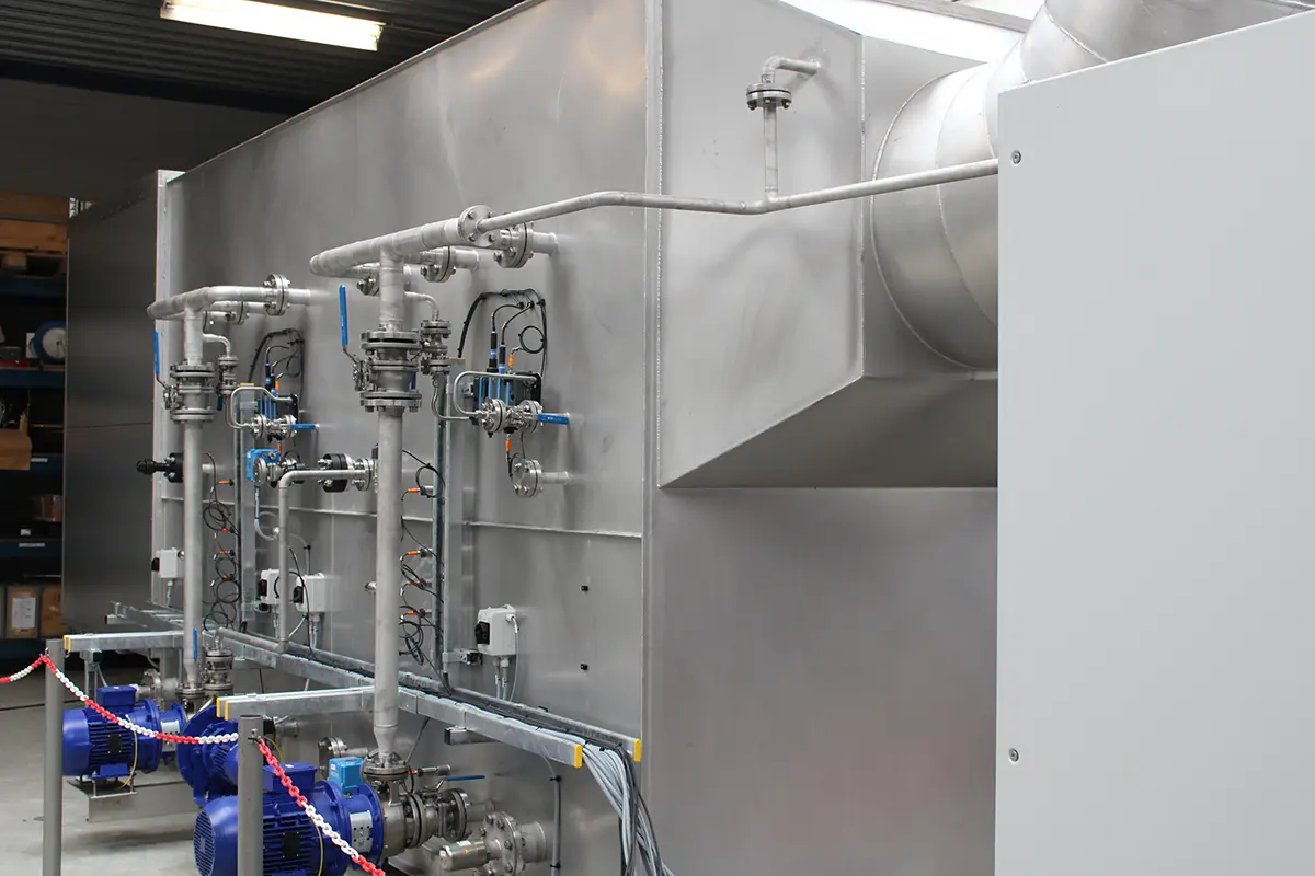
Pump
The pumps (KSB) are directly installed on the liquid buffers of the washing section and circulate the liquid. The flow rate and pressure of the pumps remain constant. These centrifugal pumps are designed in a block construction format. To monitor the pump flow and pressure, the pumps are equipped with flanged manually operated ball valves and a flow switch in combination with a pressure transmitter, both manufactured by Endress+Hauser, on the discharge side. If the pump flow rate decreases compared to the initial flow rate, it could indicate clogged nozzles. Conversely, if the pump flow rate increases, it may suggest worn nozzles or potential leakage.
Control cabinet with PLC
The setup includes a galvanized steel Rittal control cabinet containing the necessary electrical components for operating the scrubber, along with its own HMI screen. Control of the entire system is managed through a Siemens S7-1500 PLC equipped with a Profinet network connection.
Measuring pH and conductivity
pH and conductivity are measured to control the dosage of NaOH in the washing liquid. In each washing section, a flow valve with sensors is installed in the pump press. The signals are managed by a controller in the control cabinet. Additionally, a conductivity measurement device is incorporated in the flow-through fixture to regulate blowdown. The fittings and instruments are manufactured by Endress+Hauser.
Level control
The wash liquid level is continuously monitored by five level switches to determine operating and alarm levels. These switches are provided by Endress+Hauser. The signals from the level switches, along with conductivity measurements, are utilized to regulate the electrically operated blowdown and replenishment valves, which are manufactured by ECON. The replenishment of clean water in the integrated buffer of each washing section is managed through flanged electrically operated ball valves. The discharge of wash water is dependent on water quality and is controlled based on conductivity. Each buffer section in the washing sections contains a flanged electrically operated ball valve with a block valve for sluice regulation. Moreover, there is a manually operated ball valve in each buffer for individual discharge control.
Dosing system
The caustic soda dosing system utilizes a double dosing box containing two separate dosing pumps (manufactured by Iwaki) to discharge the required amount. A drip tray at the bottom of the cabinet, equipped with a leak sensor, ensures safety. Additionally, the dosing cabinet features an emergency stop and light switch for the internal LED lighting. Flexible chemically resistant double-walled plastic hoses connect the dosing box to the injection points on the liquid buffers of the scrubber. The 12 mm PTFE hose within the double-walled flexible hose serves as a return to the leak detection system in the dosing cabinet.
Ventilator
The centrifugal fan, constructed from stainless steel 316L and manufactured by Siemens, is positioned on a box frame at the gas discharge of the scrubber. Its primary purpose is to offset the pressure drop throughout the scrubber system. Enclosed within a sound-insulating casing, the fan is directly integrated into the scrubber structure.